��Main uses and scope of application��
CE6-12/24 AC High Voltage Load Switch (hereinafter referred to as Load Switch) is a new type of gas-producing indoor high voltage load switch. It is suitable for three-phase AC power system with 50 Hz AC and 12/24 kV rated voltage. It is used as interrupting load current and switching short circuit current.
��Normal working conditions��
2.1Ambient air temperature�Q+40�桢�R-25�棻
2.2 No more than elevation l000m
2.3 Relative humidity: Daily mean�Q95%��Monthly mean �Q90%
2.4 Surrounding air should not be obviously polluted by corrosive or flammable gases and steam.
2.5 Non-recurrent violent vibration
��Main specifications and technical parameters��
3.1 The main specifications are detailed in the table l
3.2 The rated parameters are detailed in the table2
3.3 Fuse Type Selection Details See Table 3
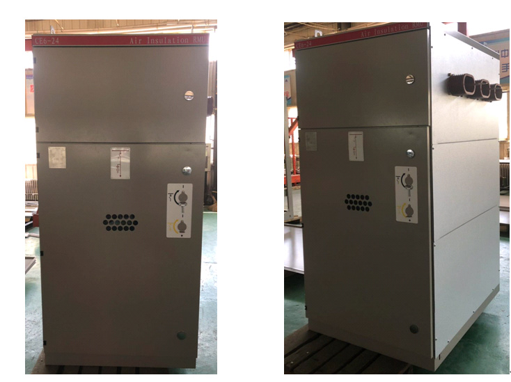
��Structure overview��
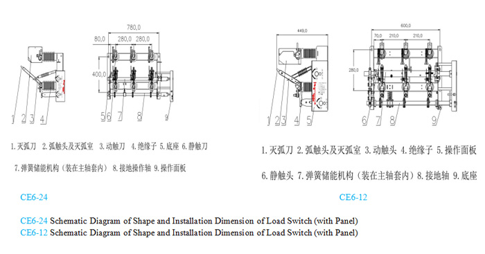
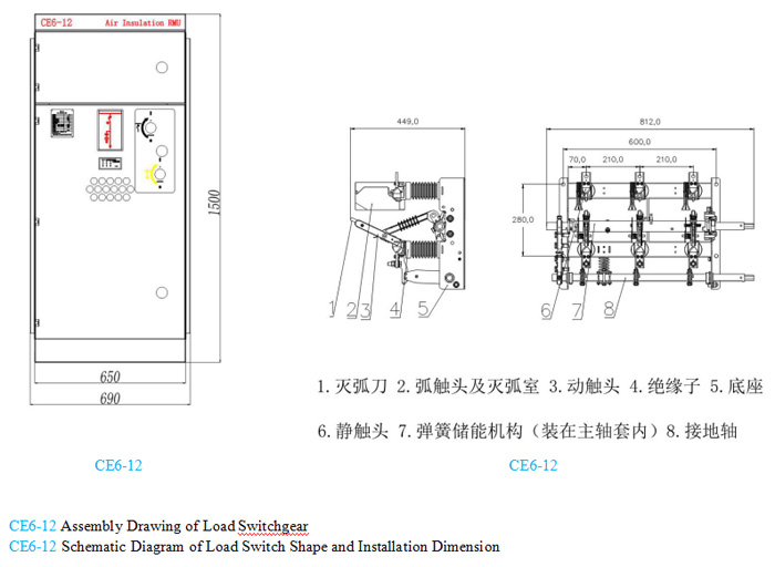
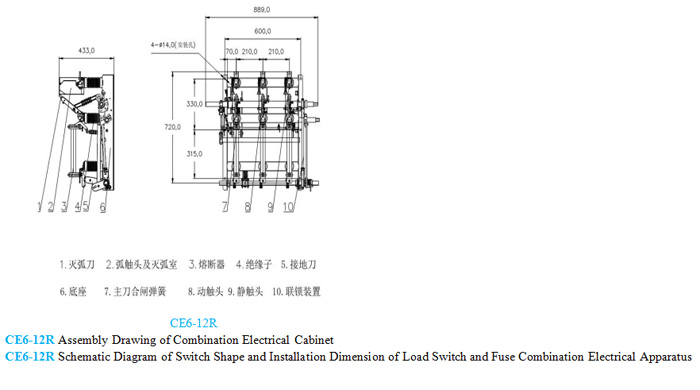
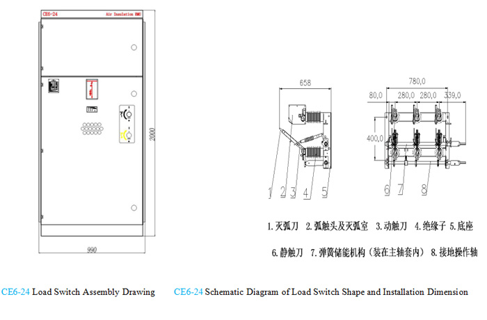
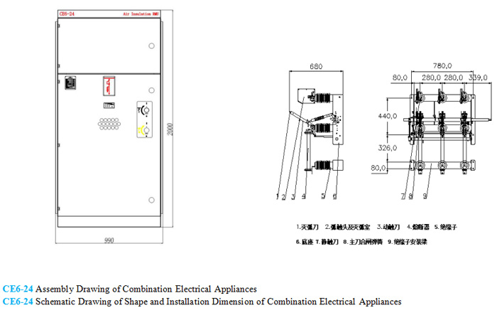
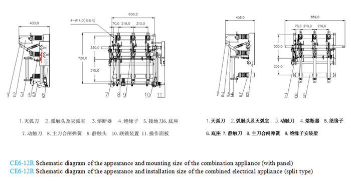
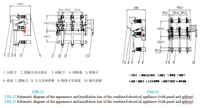
Load switch is composed of support frame, insulator, dynamic and static contacts, arc extinguishing knife, arc extinguishing device, transmission mechanism, etc. Load switch plus fuse combination is composed of load switch part, fuse, spring energy storage mechanism, etc. Grounding switch can be integrated with load switch and fuse combination, and has interlocking function with load switch.
��Function��
5.1 Closing operation:
When manual closing, the energy storage shaft is rotated clockwise with the operating handle. When the handle rotates more than 60 degrees, the spring releases energy, and the moving contact and the static contact close quickly.
5.2 Switching operation and arc extinguishing principle ��
Manual switch-off ��When the energy storage shaft is rotated counterclockwise with the operating handle, the spring releases energy when the rotation exceeds 60 degrees. During the opening process, the main contact cutter is first disconnected, and then the arc contact cutter is instantaneously disconnected. When the arc contactor is disconnected, the arc is generated, and the arc is rapidly elongated on the inner wall of the arc extinguishing device. Under the action of high temperature of the arc, the gas is generated inside the arc extinguishing device, which causes the arc to extinguish.
5.3 Load switch equipped with current limiting fuse with impactor has automatic release device.
Even if the fuse is not fully fused, the load switch will automatically switch off. After replacing the fuse, the energy storage shaft must be operated counter-clockwise to reset the mechanism before re-closing.
5.4 Load switch equipped with grounding switch realizes interlocking through interlocking mechanism to avoid misoperation.
5.5 When the fuse is selected to cooperate with the integral load switch, the split load switch can be selected at the wrong time.
5.6 The load switch with automatic tripping device can be equipped with a shunting coil to achieve rapid switching.
��Shape size and installation��
6.1The outline size is shown in the following figure.
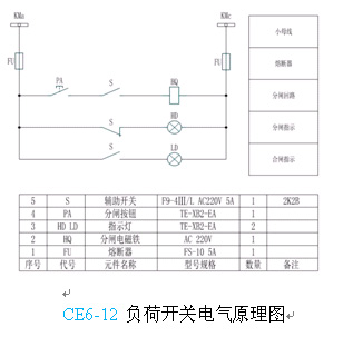
6.2Load switch equipped with electric braking device, see electrical schematic diagram.
��Installation and commissioning��
7.1The product has been debugged and tested before leaving the factory. Do not adjust and operate the switch without authorization before installation.
7.2 Load switch should be installed on vertical wall or metal frame, with 4 to 6 M12 bolts, fixed in the installation hole position.
7.3Connecting switch busbar, copper bar should be leveled before installation, fastened with bolts to prevent the switch from being damaged or deformed by excessive force, affecting conductivity and contact.
7.4The switch is equipped with CS6 or disc manual operation mechanism. When the handle is up, it is in the closing position and when the handle is down, it is in the opening position.
7.5After installation of load switch operation mechanism and mother money, it should be operated at least five times. Its moving parts should be flexible, its conductive contacts should be good, and the dynamic and static contact knives should not be dislocated due to busbar installation.
��Use and Maintenance��
8.1 After unpacking, check whether the product and random technical documents are complete according to the packing list, and check whether the product is damaged during transportation and storage.
8.2 Clean up the dust on the product and wipe the insulator and grounding part clean ��
8.3 Conductive and mechanical friction parts, coated with neutral vaseline��
8.4 After installation, check whether the wiring is correct and good grounding is reliable��
8.5 Periodic inspection and maintenance should be carried out in operation, once a year, and comprehensive overhaul should be carried out after 20 rated loads are cut off.��
8.6 Maintenance should be carried out without electricity, and insulators and contacts should be inspected��
8.7 Operators must be familiar with the performance, structure and installation of this load switch��
Main Specifications
|
Name |
TYPE |
All Models |
DS the earthing switch is on the incoming side |
DX��Flip chip��The earthing switch is on the outgoing side |
L Interlocking device |
R Fuse |
RA |
F |
|
Load switch |
No release |
CE6-12 |
|
|
|
|
|
|
|
CE6-12DSL |
�� |
|
�� |
|
|
|
||
|
CE6-12DXL |
|
�� |
�� |
|
|
|
||
|
CE6-12R |
|
|
|
�� |
|
|
||
|
CE6-12DSLR |
�� |
|
�� |
�� |
|
|
||
|
CE6-12DXLR |
|
�� |
�� |
�� |
|
|
||
|
With strike release |
CE6-12RAF |
|
|
|
|
�� |
�� |
|
|
CE6-12DSLRAF |
�� |
|
�� |
|
�� |
�� |
||
|
RAFCE6-12DXL |
|
�� |
�� |
|
�� |
�� |
Rated reference data
|
Rated voltage kV |
|
Maximum voltage |
Rated Electric current |
1min Power frequency withstand voltage kV |
1s Thermally stable Electric current��Effective value��kA |
Dynamic stable electric current��Peak value��kA |
Short circuit close&open |
Rated close&open |
Rated Transfer Electric |
|
10 |
|
12 |
125 |
42/48 |
25 |
50 |
31.5 |
630 |
1700 |
|
|
630 |
42/48 |
25 |
50 |
50 |
630 |
|
||
|
20 |
|
24 |
125 |
50/60 |
25 |
50 |
63 |
630 |
900 |
|
|
630 |
50/60 |
25 |
50 |
63 |
630 |
|
Fuse select model table
|
Transformer capacity kVA |
100 |
125 |
|
160 |
200 |
250 |
300/315 |
400 |
500 |
630 |
750/800 |
1000 |
1250 |
1500/1600 |
2000 |
2500 |
|
12kV |
10 |
10 |
|
16 |
20 |
25 |
31.5 |
40 |
50 |
63 |
80 |
80/100 |
100/125 |
125/160 |
160/200 |
250 |
|
24kV |
3.15 |
6.3 |
|
10 |
10 |
16 |
16 |
20 |
25 |
31.5 |
40 |
50 |
63 |
80 |
100 |
125 |
Replace this table of medium voltage switch��CE6-12/24 Indoor high voltage AC load switch��contained��Main Specifications��Rated reference data��Fuse select model table��